Request a Quote

If you are interested in our work, do not hesitate to contact us, we will be happy to provide you with further information.


    info@rfspin.com

    Request a Quote

    If you are interested in our work, do not hesitate to contact us, we will be happy to provide you with further information.


      info@rfspin.com

      Request Support

      If you need any kind of assistance with your RF SPIN product, we will be happy to help you.


        info@rfspin.com

        RF SPIN

        Broadband Antenna Solutions

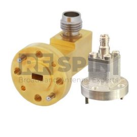
        AWC12EFW

        Waveguide to Coax Adapter

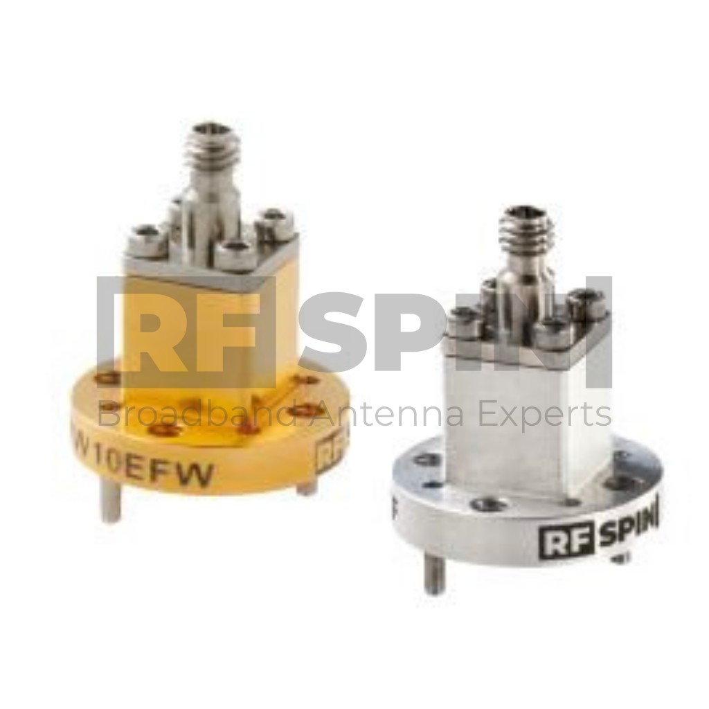
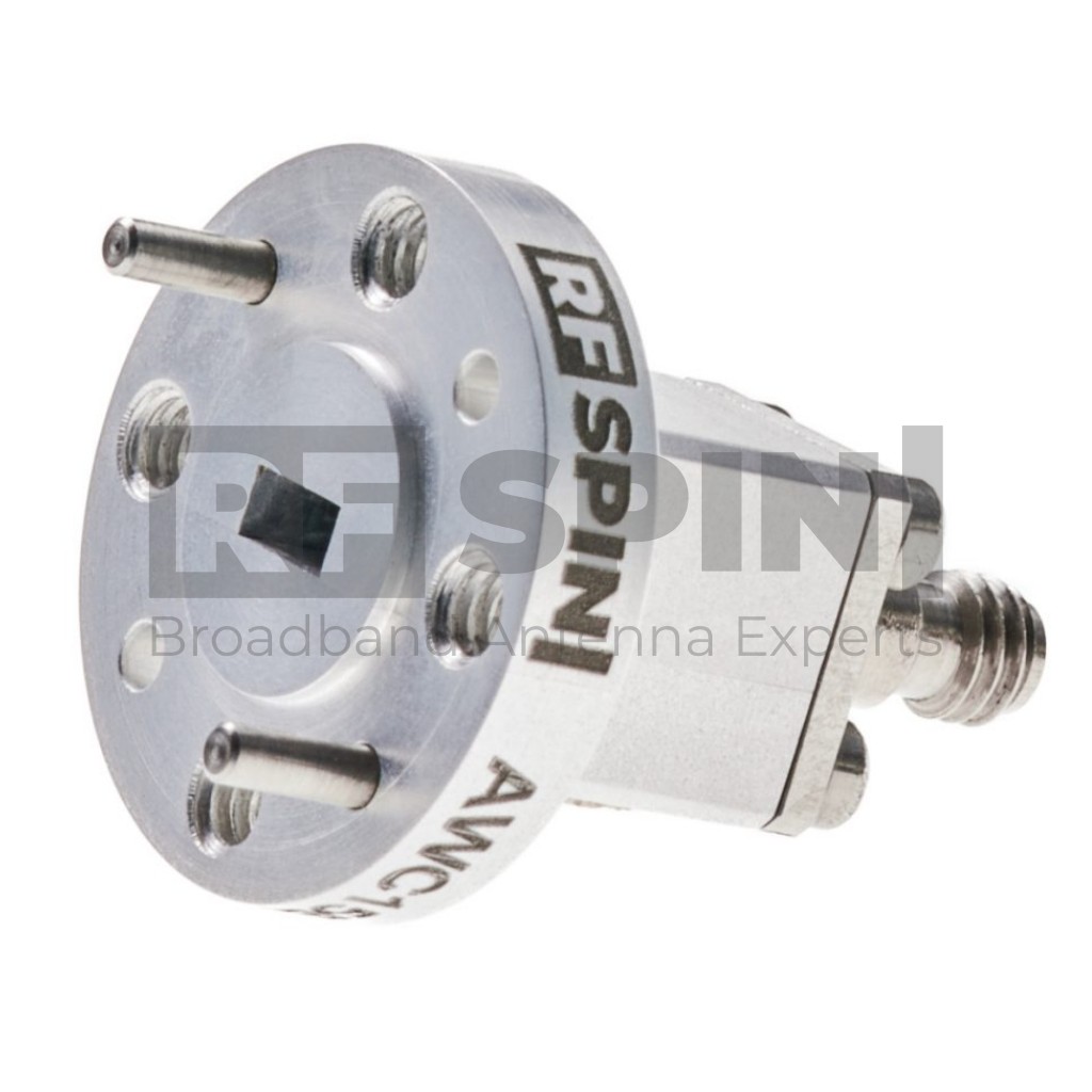
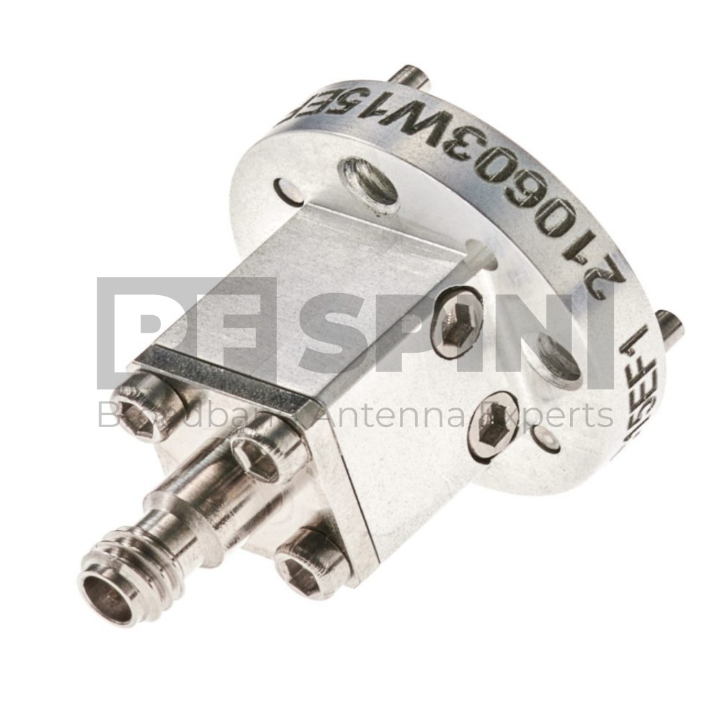
        This Waveguide to Coax Adapter AWC12EFW is manufactured with an end-launch design. RF SPIN is using only high-grade aluminum and design with the fewest components to ensure top quality and superb performance. This AWC12EFW has waveguide size WR-12 and flange. Using a great quality 1.00mm female connector that is 50 Ohm is a matter of course.

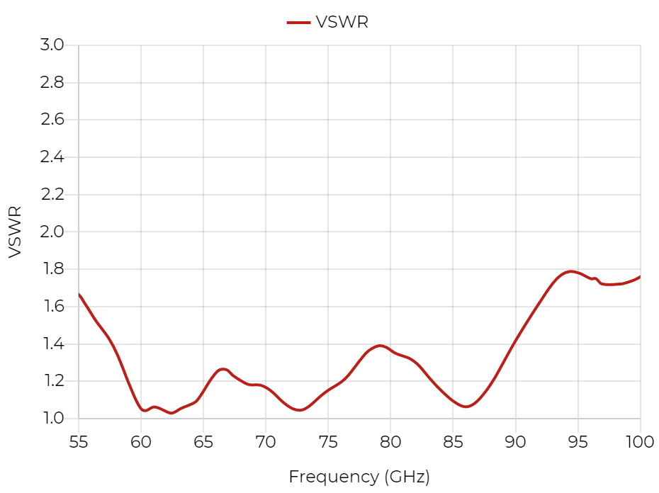
        Waveguide to Coax Adapter covers a frequency band from 60 GHz up to 90 GHz ensuring the extra performance of VSWR lower than 1.35 and low insertion loss.

        Manufactured with RF SPIN’s SPM Technology to achieve the best mechanical and radio parameters.

        Availability: Most products are on stock. Please contact us for more information or large quantity orders.

        Features and Specifications

        Technical Performance

        • Wide bandwidth
        • Low return loss
        • Individual calibration

        Design and Surface Treatment

        • Corrosion-resistant coating

        Manufacturing Technology

        • Manufactured using a high grade aluminum alloy
        • Extremely durable
        • High quality 1.0mm type coaxial connector

        Product Packaging Includes

        • Waveguide to Coax Adapter

        Product Parameters

        Product identification

        • Product Name AWC12EFW
        • Product Category Waveguide to Coax Adapter

        Electrical specifications

        • Frequency Range 60 GHz – 90 GHz
        • VSWR (max.) 1.35
        • VSWR (avg.) 1.25
        • Impedance 50 Ohm
        • Insertion Loss (max.) 0.6 dB
        • Connector 1.0mm (female)
        • Waveguide Size WR12
        • Waveguide Flange UG-387/U flange
        • Power (CW / Peak) 4 W / 8 W

        Operating conditions

        • Rated Temperature Range 0°C – +50°C
        • Storage Temperature Range -20°C – +70°C

        Parameters and Performance

        Typical parameters

        VSWR

        AWC12EFW - VSWR

        Packaging and Accessories

        What's in a box

        • AWC12EFW Device
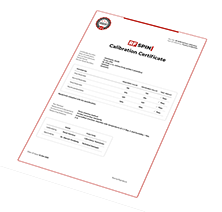
        • Factory calibration certificate
        • Full calibration report of each antenna
        • QR code accessing online portal
        • Calibration test dataset (available online)

        Accessories

        • Standard mounting flange
        • Factory calibration report

        Other Similar Products

        AWC10EFW
        Waveguide to Coax Adapter
        Frequency Range

        75 GHz – 110 GHz

        VSWR (avg.)

        1.25

        Impedance

        50 Ohm

        Connector

        1.0mm (female)

        Power (CW / Peak)

        4 W / 8 W

        Polarization

        Linear

        AWC15EFV
        Waveguide to Coax Adapter
        Frequency Range

        50 GHz – 67 GHz

        VSWR (avg.)

        1.25

        Impedance

        50 Ohm

        Connector

        1.85mm (female)

        Power (CW / Peak)

        5 W / 10 W

        AWC15EFW
        Waveguide to Coax Adapter
        Frequency Range

        50 GHz – 75 GHz

        VSWR (avg.)

        1.25

        Impedance

        50 Ohm

        Connector

        1.0mm (female)

        Power (CW / Peak)

        4 W / 8 W